You can build an Online UPS which is better than commercially available UPS systems using Victron Energy parts. It will better protect your equipment from bad utility power because power fluctuations and surges will never be passed through to your equipment, and you can extend the run time to whatever you need by adding more batteries.
GTIS has been recommending the various products from Victron Energy because they appear to be well built, robust and are becoming readily available in most countries. Victron is located in Europe and their products can be ordered in nearly every voltage specification as well as plug style (NEMA 3, UK, AU/NZ, etc). The Phoenix inverter has a European safety rating of EN-IEC 60335-1 / EN-IEC 62109-1 / UL 458 (3).
 The first step into designing an Uninterrupted Power Supply (UPS) system using an inverter is to have a good understanding of the power (Volts x Amps) being used on each device that would run from this inverter. One of the simpler ways to do this is to measure the power being used by each device (network servers/switches, computers, Wi-Fi routers, etc.) with the Kill-a-watt meter. Do not simply use the watts given on the equipment data label because this is typically a maximum wattage, the device generally uses less than what is on this label. Worse case, using the data label wattage your UPS inverter will be “oversized”. Your device might list its power usage as either watts (W) or volt-amps (VA).
Components
There are five basic components needed to build this UPS.
- Inverter – 12 volt, VA size determined by the load being powered. If your total loads are greater than 1000 watts, you should consider a 24 Volt inverter.
- Charger(s) – able to supply power for the Inverter load plus charge the battery.
- Cables – sized for minimal loss due to resistance/heat.
- Overcurrent protection for wiring (fuses or breakers.)
- Battery – 12 volt, 100 – 200 Amp-Hr
Inverter
We chose to use a 12V DC model inverter for this system in an effort to keep the wiring simple and avoid having to parallel multiple batteries. The inverter model used in this example is the Phoenix 12V 800VA, 230V output. Victron Part number: PIN121800400.
To adequately determine the inverter size, you would add up all loads (VA or Watt). From this total, you will also want to add a little extra margin (+25%; VATOTAL x 1.25) onto the total wattage loads for those continuous loads and any additions in the future. If your total continuous loads are greater than 1000 watts, our recommendation is to consider using a 24V model Inverter with two 12 Volt batteries in series.
Visit the Victron Energy “Inverter VE.Direct webpage, find the inverter model desired, and examine the datasheets carefully! For our inverter, the rated power at 25ο C is 800 VA, but only 650 W; and further reduces to 560 W at 40ο C. The goal is to remain under both the continuous VA and continuous Watt ratings of the Inverter at the ambient temperature you expect. If you know the VA of the loads compare that to the VA limit of the inverter, if you only know the watt rating, compare that to the watt limits listed for the inverter. If you have included a 25% margin you should be fine. Do not be fooled by the “peak power” rating, this is the maximum power the inverter can deliver for a very brief amount of time.

With this total, you can identify which inverter model that would satisfy your needs. If the total continuous VA (watt) load is greater than the continuous power rating, you would select the next higher rated model.
Charger(s)
 Victron energy offers a well built, affordable charger. These “Blue Smart IP22 chargers” (bluetooth) use an adaptive (6 stage) charging algorithm for charging the battery and acting as a power supply. The adaptive feature will automatically optimize the charging process relative to the way the battery is being used. This charger is able to charge most any battery chemistry (Flooded, AGM, Gel, LiFePO4).
We have been using the 30 Amp IP-22 Blue Smart chargers. The 230v single output model is part number BPC123047002. There is also a 3-output version which costs a little more – the only difference is in the number of DC outputs available. Having looked at them both, the 3-output model only supplies one negative (black wire) terminal, so there isn’t any real advantage for the additional expense of the 3-output model. For the 800 VA UPS system, at least two IP22 12 V, 30 Amp chargers are needed.
Why do I need two chargers?
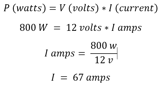
The chargers need to provide enough power to supply the loads, but at the same time charge the batteries. For these calculations we’ll treat VA identical to W. One Blue Smart IP22 charger can only supply up to 30 amps at 12 volts (360 VA). For this 800 VA inverter, you will need a total of 67 DC Amps from the battery / chargers to supply the 800 VA at 230 volts, more than one charger can produce.
Two Blue Smart IP22s can produce a total maximum of 60 amps. (60A x 12V = ~720 VA) So, this system is limited by the 2 chargers to ~640 VA of continuous load. Below 640 VA these two chargers will have enough excess to charge the batteries at a reasonable rate (80 VA or ~6.5 A). If the total continuous loads are between 640 – 800 VA, you would need a third Blue Smart IP22 charger. However, if your continuous loads are this high, you should also choose the next higher Victron 1200 VA rated inverter to maintain some margin.
Note: Within the setting of these chargers, there is a “VE smart networking” where up to ten chargers on the VE Smart network can be synchronized to act as one charger.
Cable (Wiring)
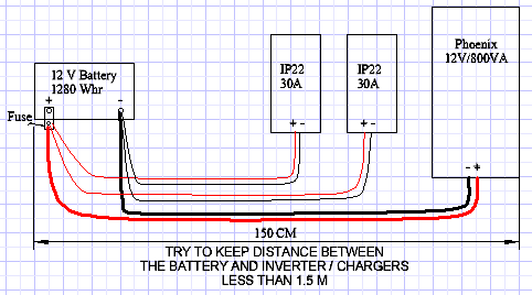
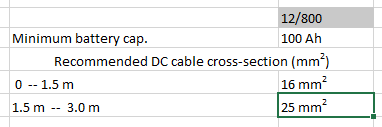
When building your UPS system, it would be wise to fully read the inverter and chargers manuals before beginning. The information contained within each will be of great help in knowing how to install each piece of equipment but also the correct fuse size and wiring sizing as it relates to the lengths of conductors. If you are not able to find the recommended minimum wire size from the following chart, the best action would be to get the next larger wire size that is available. Never go with a smaller wire size than has been recommended! The following chart has been taken from the Victron manual for the Phoenix inverter.
Battery Cable size
The 800 VA Inverter will have two IP-22 Chargers, so you will need two sets of positive (red) and negative (black) conductors at least 6 mm2 that are rated for 30 amps of current. Locate the equipment as close together as possible to reduce the wire length.
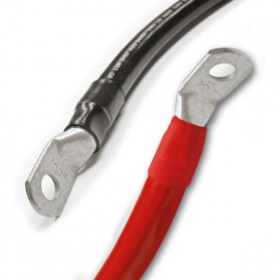
Incidentals – You will also need to have terminals installed on these battery and charger cables. Because of the wire size, these terminals may require special tools to crimp them properly. It has been suggested that you request that these battery terminals be installed by the wire supplier (solar store) when purchasing the various conductors.
Note: The Phoenix inverters and the Blue Smart IP22 chargers are fitted with their own “internal’ fuses, this is intended to protect the inverter or charger, not intended as a system fuse. You still need a fuse or circuit breaker at or very near the battery terminals.
Overcurrent Protection
The selection of a system fuse and fuse holder will depend on what your local Victron solar supplier has in stock. The fuses should be rated for 32V DC or higher and capable of interrupting rating of 5000 amps or more. The system fuse size should not be smaller than 100 Amp and could be as high as 150 Amps. 
We have used the Bussmann MRBF style terminal fuse holder and fuses. Many other options for overcurrent protection are available, see the GTIS store for examples.
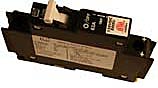
We highly recommend the excellent MNEPV breakers from Midnite Solar if you can get them. They mount on a DIN rail and come in a variety of amperage ratings at a bargain price.
Battery(s)
The Victron inverter manual recommends a minimum size battery (Amp-Hour) for each of their inverters. The 800 VA Phoenix inverter minimum battery size is 100 Ahr (1200 Whr). The size of the battery is a delicate balance where it will determine your UPS run-time when power is out, but it also has to be able to be fully charged by the chargers. The larger the battery(s), the longer the UPS will operate when power is lost.
For help with choosing which battery, there are two recommended sources.
See the GTIS website – self help about batteries. or
Read about the advantages of Lithium or AGM article by Victron Energy: Lithium vs AGM?
Calculating the UPS run-time.
The battery will be rated for the energy (power x time) it can deliver, in our case we have a 1280 W-hr battery (12.8 V * 100 amp-hours). For a UPS power load of 640 Watts, this would approximately yield a run time of 2 Hours when fully depleting the battery’s energy.
One or more batteries?
If longer run time for the UPS is needed, you can parallel two batteries – which would in theory double your run time. A third could be added, but this is generally the limit due to the tendency for batteries to get our of balance with each other. With larger battery banks, recharge time after a power outage will take longer. If your continuous loads are close to the 640W limit, consider adding a third IP 22 battery charger to get your batteries charged within a few hours and ready to handle the next power cut.
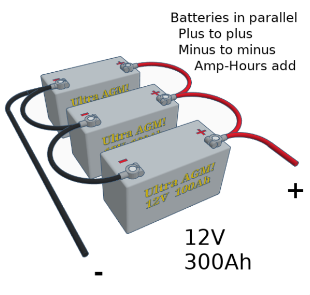
Multiple batteries
Attaching batteries in parallel must be done properly to ensure that all batteries remain equally charged. The batteries should each be individually fully charged before connecting them in parallel. Begin with two battery cables (with terminal ends) of equal length. The cables should be sized as large as practical using at least (not smaller than) 25 mm2. Use a wire length approximately 40-50 cm. Connect the inverter (charger) positive to one battery positive post, then connect the inverter (charger) negative to the other battery’s neg post (see image below).
There are four common types of batteries available, but each has its own needs. To read more about batteries, see the GTIS website self help page.
- Flooded Lead-acid
- AGM (Deep cycle)
- Gel – generally not recommended.
- Lithium-Ion – there are many advantages of using a LiFePO battery besides the fact that they are much lighter although they cost a little more up front. Three important advantages are:
- Their lifetime is not degraded by tropical heat nearly as much as all types of lead-acid batteries are.
- These batteries do not “off-gas” and will not corrode electronics that are close by.
- They can last up to +10 year life span — which makes them cheaper in the long run.
Building the UPS
PARTS LIST NEEDED
| QTY | Description | ITEM number |
| 1 | 230V AC surge protector – with 2 or more outlets (to plug the chargers into) | |
| 1 | Battery 12V, 100 AH LiFePo3 or alternatively a Deep cycle sealed Lead acid 12V battery. | |
| 1 | Victron Energy Phoenix VE.Direct 800W, 12V, 230 VAC | PIN121800400 |
| 2 | Victron Energy Blue Smart 12V, 30A 230 V Chargers | BPC123047002 |
| 1 | Fuse block, BlueSea or equivalent | CBBF-MBC |
| 1 | Fuse, 150A, BlueSea or equivalent | CBBF-100 |
| Either | For Battery to Inverter cable lengths 1.5 meters or less. | |
| 2 | Inverter cables: 16mm2 (#6 AWG) 1Red & 1Black x 1.5 m | |
| 2 | compression ring terminals, 8 mm (5/16”) stud, for the 16mm2 cables | |
| 4 | Charger wires: 6mm2 (#10 AWG) 2Black & 2Red x 1.5M (5 Ft) | |
| 4 | Ring Terminals, 8 mm (5/16”) stud, for 6mm2 charger wires | |
| 1 | Grounding Wire: 6mm2 (#10 AWG) Green/Yellow x 1.5M (5 Ft) | |
| OR | For the Battery to Inverter cable lengths up to 3 meters | |
| 2 | Inverter 20mm2 (#4 AWG) Red/Black x < 3 m (not greater than) | |
| 2 | compression ring terminal, 8 mm (5/16”) stud, for the 20mm2 cables | |
| 4 | Charger wires: 6mm2 (#10 AWG) Black/Red x 3 m | |
| 4 | Ring Terminals, 8 mm (5/16”) stud, for 6mm2 charger wires | |
| 1 | Grounding Wire: 6mm2 (#10 AWG) Green/Yellow x 3m | |
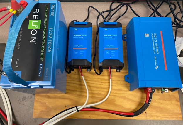
Unbox the Victron Equipment
- 800 VA Phoenix inverter
- IP22 30A Smart chargers – both are required for this system.
- A 1.5 m battery cable and two sets of 1.5 m charger cables.
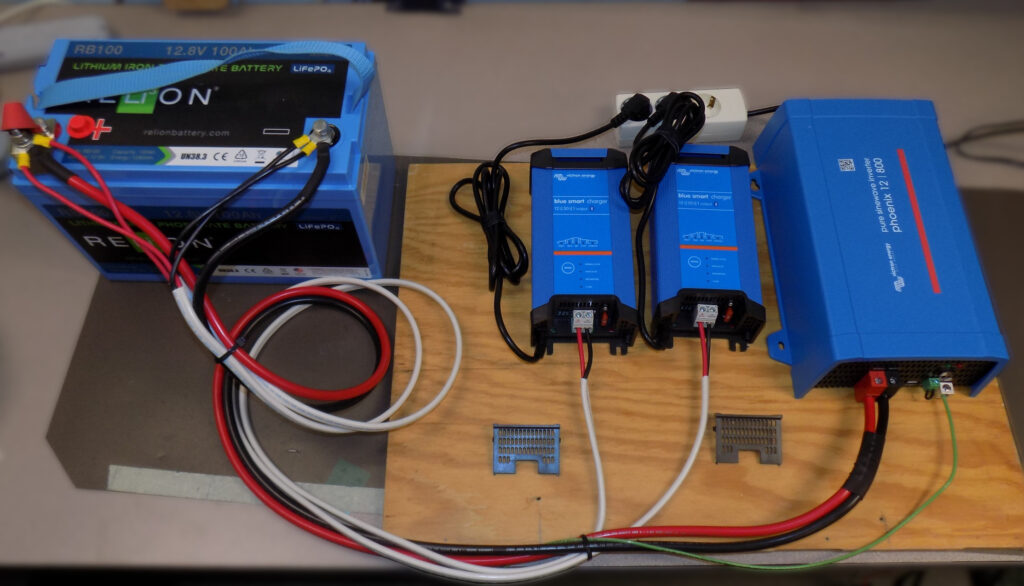
Install equipment onto plywood / board
- Locate the battery as close to the inverter as practical.

- Ensure that the Phoenix inverter is switched OFF.
- Note: the IP 22’s do not have an on/off switch, these are simply plugged in to operate. Leave them unplugged until after connecting to the battery.
- To protect the IP 22 battery chargers, they should be plugged into a power strip with surge protection built in. This can be mounted on the board, or nearby depending on your needs.
Prepare the Battery Cables:
For cable lengths up to 1.5 meters, use 16mm2 battery cable.
For cable lengths between 1.5 – 3.0 meters, use 20 mm2.
Battery terminal end – use a 8 mm ring terminal for the battery cable size (16mm2 or 20mm2). If you are purchasing the battery and charger cables from a local supplier, it is suggested that you have them crimp the ring terminals onto these cables. We strongly recommend using fine stranded marine tinned cable. This cable is suitable for all environments, highly flexible and easy to work with.
-
- Strip approximately 10 mm from one end of both the black & red conductors.
- Insert each conductor into an appropriately sized (battery lug) ring terminal. The ring terminal should fit a 8 mm stud.
- Crimp these terminals onto each conductor end.
Inverter end:
-
- Strip approximately 10 mm from the end of both the red and black conductors.
- Using a soldering iron and solder, tin the end of these wires. Do not allow the solder to go under the insulation, only tin the ends of these conductors to keep the wire strands together. Add just enough solder to flow into the conductors without globs of solder.
- Alternate – Use a ferrule crimped on with a hex crimp tool.
If you do not have access to a soldering iron, the conductors can go into the inverter but ensure all wire strands are inside the Inverters terminal – to prevent any short circuits.
Prepare the IP22 Charger cables
-
- These two IP22 charger cables will use 6mm2 conductors.
- Charger cable – battery end – use a 8 mm ring terminal.

- Strip approximately 10 mm insulation from one end of the charger’s black & red conductors.
- Crimp on a ring terminal for this wire size with an 8 mm ring terminal
-
 Charger cable – IP22 charger end – if available, crimp sleeve.
-
- Strip approximately 10 mm of insulation off the opposite end of the charger’s black & red conductors.
- If available, crimp a terminal sleeve on these conductors – this will keep the wire strands together. If not available, you can skip this step.
- If you are not able to crimp on sleeves, you could solder tin these conductor ends to keep the wire strands together.
-
Connect the Inverter
-
- Make the first connection at the Phoenix inverter.
- Insert the tinned end of the battery cable into the Phoenix inverters terminals.
- Connect the black 16mm2 or 20mm2 conductor to the black connection on the Phoenix inverter.
- Connect the red 16mm2 or 20mm2 conductor to the red connection on the Phoenix inverter.
- Using a slotted screwdriver, carefully tighten these terminals onto the black & red conductors.
- At this time, do not attach the opposite end of these cables to the battery.
If available, connect a 6mm2 green/yellow wire to ground lug on Inverter to the building ground.
Connect the IP22 Chargers:
Using the two 6mm2 black and red twin conductor cable, connect the sleeved end of the black wire to the black terminal and the red wire to the red terminal on each of the IP22 chargers. Using a slotted screwdriver, carefully tighten these screws onto the black & red conductors.
Connecting to the battery:
Be careful so that wrenches do not touch both the battery positive & negative terminals.
-
 The ring terminal ends of the battery cable and charger cables will go on to the battery.
- First, connect all the black battery (-) ring terminals to the battery negative.
Do this for the Phoenix inverter, the IP22 chargers, and any accessories you have. - Carefully tighten the battery neg (-) terminal.
- Connect all other positive (+) cables on the battery positive (+) post.

- First, attach the fuse holder and the 150A fuse to the battery positive post. All the ring terminals attach to the top of this fuse, not the battery post.
- Then attach the large positive ring terminal from the inverter to the pos (+) post on the Fuse.
- On top of that, attach all the smaller red positive (+) ring terminals on the fuse and carefully tighten this nut with a 13 mm wrench on the battery positive (+) fuse.
- Cable management: Arrange the cables and secure them to the plywood so they will prevent them from being moved around or so not put any stress on the inverter or chargers terminals.
Optional Remote Monitoring can be added
OPTIONAL: With some additional equipment, you could be able to connect your UPS to the Internet and monitor it remotely on the VRM Portal. To do this, you would also need to purchase the Cerbo-S GX (part number BPP900450120) and one VE Direct cable (part number ASS030530209). If you have the optional Cerbo-S GX device, also attach its black wire to battery negative and the red power wire to the battery positive +. At this time attach the VE.Direct cable between the Phoenix inverter and the Cerbo-S GX. This Victron proprietary connector only fits into its correct terminal. Additional setup in the Victron Connect app are required for the Cerbo-S GX. Those instructions are in the Cerbo GX manual or will have been provided if this option is requested. See YouTube for instructions on connecting with the Cerbo GX.
Commissioning the Victron system
Download the free VictronConnect App from https://www.victronenergy.com/support-and-downloads/software. Enable bluetooth on your device and open the Victron Connect app.
Commissioning the Phoenix inverter
With the Phoenix connected to the battery, turn the switch to the “on” or “I” position. The inverter is ready to begin using with the factory settings. For the LED indications, see the Phoenix 12/800 manual for normal LED definitions and troubleshooting.
To make any changes to the Phoenix inverter, you must have a VE.Direct to USB cable and the VictronConnect App running on your computer, smart phone, or tablet. Victron Connect will support both Android and Apple devices.
Commissioning the IP 22 Chargers: (do this for each IP22 charger).

The Mode Button is a circle on the top of the charger
For setup tutorial, see Setup IP22 (you tube). Generally, the only setting you will need to change is the battery mode for chemistry (Li-Ion, Lead acid).
Plug each IP22 Charger into a 230 V receptacle.
The LED lights will begin to flash.
If there are no LEDs displayed, verify that the internal fuse has not blown.
If you are using a LiFePO battery, once the IP22 is powered ON, press the “mode” button until “Li-Ion” LED light is lit.
The IP22 chargers are ready to use individually, but one important setting change you need to make is to synchronize these two chargers. You need to change the configuration using the VictronConnect app via bluetooth with a smartphone, tablet or computer.
CAUTION – changing the charger settings will change how the battery is being charged. Do not make any changes unless you have read and fully understand the Victron IP22 Manual. Any changes to one charger, must also be made on the second charger.
Configuration using VictronConnect app
-
 Make sure bluetooth is enabled on your smartphone, tablet or computer.
- Open the VictronConnect App on your device.
- In the VictronConnect App, under the “local” tab, look for the IP22 chargers.
- Select one of the chargers. (The first time you connect with any Victron equipment, you will need to enter the passcode which is “000000” six zeros. You will be prompted to changed this passcode. If you do change the code, make sure you record the new passcode.)
- On this home screen you will see the charger status.
- If you tap on the “settings” (gear) at the upper right, you can adjust the configuration.


-
- Scroll down the list until you see “VE.Smart networking” and select that.
- Set up the bluetooth IP22 VE Smart networking (this enables multiple IP22 chargers to coordinate their charging algorithm so the load is shared between them.)
- Select “create network”
- Name the network something you will recognize – this is only used between the Victron equipment.
- Exit back to the main menu of the Victron Connect, and select the second IP 22 charger.
- Click on the gear in upper right
- Go to bottom of the menu list to “VE Smart networking”
- Click on “join existing network”
- from the list, select the network name created above.
- Select “OK” , now you can exit out of Victron Connect.
- From this point forward, these two (or more) chargers will synchronize their charging for the battery.
Available in our web store
If you don’t have a Victron Dealer handy, the system described and pictured in this article is available for sale in our web store.